Connect and Configure
DTMF4 Connect and Configure
This guide will walk you through setting up your DTMF relay board.
Set Configuration Mode
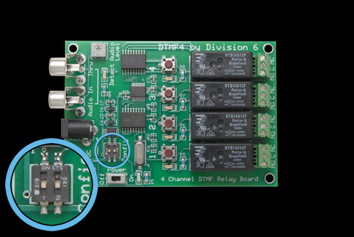
The DTMF4 has a set of DIP switches you can use to select which channels the board responds to. This allows you to have up to 3 boards (12 channels) individually controlled by a single DTMF soundtrack.
| DTMF4 Mode Settings | |
|---|---|
Mode 1 |
Relays 1-4 respond to channels 1-4 |
Mode 2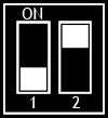 |
Relays 1-4 respond to channels 5-8 |
Mode 3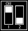 |
Relays 1-4 respond to channels 9-12 |
There is no need to turn the board off to change modes; you can reconfigure it at any time.
Connect Power
There are two power connectors on the board.
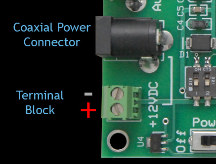
If you ordered one of the optional power supplies with the board, it would connect to the coaxial power connector. It’s a 2.1mm (center positive) connector in case you want to use your own power supply.
You also have the option of connecting 12VDC via individual wires (14-30AWG) to the terminal block.
Whichever connector you are using, the terminal block makes a handy power source for any 12VDC devices you are controlling with the board. Just run wires from the terminal block to the relays and devices.
Connect Audio
The DTMF4 board is designed to connect to line-level audio sources. For example, the audio output in the back of a home CD or DVD player. A headphone jack will also work, but you might have to adjust the volume until the board is decoding the DTMF tones reliably (start at the half-way point). To make the connection, you’ll need a cable that goes from whatever connector your audio source has to an RCA connector.
Note: The DTMF DVDs Division 6 carries use the right audio channel for control tones, so you’ll need to hook your DTMF boards to the right (red) audio output on your DVD player.
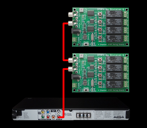
Connect the audio source to the Audio In jack on the board. If you’re using more than one board, connect the Thru jack on the first board to the Audio Injack on the next board. It doesn’t matter what address order you connect the boards as long as they are all in the chain.
Adjust the Audio Level
The DTMF4 ships with the audio level adjustment set in the center position. This will work just fine for most line-level signals. If your audio source is too loud or too quiet, you may need to adjust the Audio Level control.

To make the adjustment, first turn the trim pot all the way down (counter-clockwise). Start playing your DTMF soundtrack. Start slowly turning the pot clockwise until the Detect LED (the green one) flashes every time there is a tone. Once you have reached this point, turn the pot up a little more. Generally this should be a good level, but you may need to keep turning the pot up until the relays respond to DTMF commands consistently.
Connect the Relay Outputs
There are a variety of devices that can be connected to the relay outputs of this board. I’ll try to give you a few examples here that you can hopefully adapt to your needs.
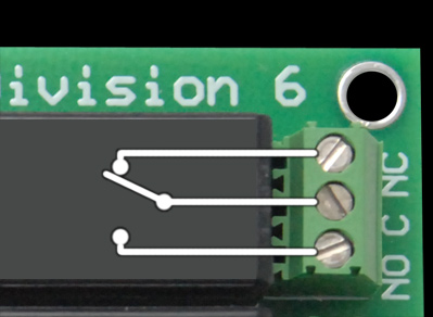
The first thing you need to know is that the “outputs” of this board are connected to relay contacts. They act as switches only. They don’t provide any power unless you connect power to them.
Some things are already set up to be activated by a button or switch. This includes things like triggering DVD players, halloween props with “Try Me” buttons, fog machines, MP3 players, etc. If you can push a button to trigger something, just replace the button with the C and NO contacts on the board.
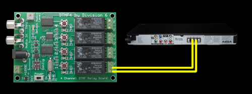
The DVD player plays whenever the two trigger contacts on the back are connected together. When one of the channels on the DTMF4 is turned on, the C and NO connections get connected together. Wire the two devices together as shown above to use DTMF tones to start a DVD playing.
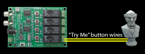
Many Halloween props have “Try Me” buttons you can press that let you see what they do before you buy them. Since any button can be replaced with the DTMF4, you can just clip the button off and connect the two wires to the board as shown above.
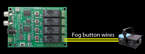
Fog machines: You push a button and fog comes out. Once again you can replace that button with the DTMF4. If you want to retain the use of your original fog button, you can hook the button and the DTMF4 output in parallel.
Some devices can’t be turned on by simply pushing a button. They need power provided to them to work. The DTMF4 can control these devices by interrupting that power.
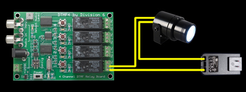
LED spotlights often run on 12VDC or some other low voltage. Power is provided to these lights from some kind of AC adapter or power supply. To provide DTMF control over these lights, interrupt one side of the power supply wiring and connect to the board as shown above.
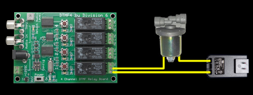
If the prop or effect you’re trying to control uses an air valve (like in this demo), you can hook it up the same way as the spotlight above. The board switches the power going to the valve, turning it on and off.
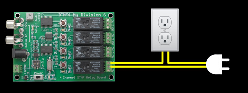
Some devices run on AC power, and the easiest way to control them is to turn the power going to them on and off. In this case we recommend wiring an AC outlet to the DTMF4 instead of cutting up the power cords on your devices.

Once you do this, all you have to do is plug whatever you want to control into the outlet.
Be careful when working with AC voltages! They can hurt! Insulate all your AC conections, and put the board in some kind of enclosure so that nobody can touch it when it’s powered up. If you really need to test something, the area on top of the board around the buttons should be safe to touch since none of the relay contact traces go near them, but it’s best to be on the safe side and just not touch the board at all when it’s connected to AC.
So far I’ve been using the C and NO connections for everything. These are the Normally Open contacts. This means that the “switch” is open (off) until you activate that channel of the board by using DTMF tones or the test button. If you want the switch to be closed (on) until the channel is activated, you can use the Normally Closed contacts (C and NC).
The above example is just like the previous AC outlet hookup, except it’s using the Normally Closed contacts. A device plugged into the outlet in this case would be on until channel 1 on the DTMF4 is activated, at which time it would turn off.
I’ve been showing everything connected to channel 1 on the DTMF board, but if you have more than one device to control, you can connect the additional devices to the Normally Open or Normally closed contacts on channels 2, 3 and 4.
Hopefully you can use one of the above examples to figure out how to hook up your props, devices and effects. If you do have any questions about your particular application, please don’t hesitate to contact us!